Dynamic Multipoint VPN
Ever wonder how to provision several hundreds of VPNs from remote offices with dynamic IP to a central site with minimal configuration? Cisco offer an elegant solution called Dynamic Multipoint VPN. With DMVPN the central site does not need to know the remote site IP in advance, it will learn it via NHRP protocol when the remote router will come up.
First we will create IP connectivity via GRE tunnels and NHRP then we will secure the GRE tunnels with IPSec.
The hub router will use a multipoint GRE interface for ease of management. That way we do not need to provision a new tunnel interface per remote office. In fact, the central router will not need to be reconfigured at all for any additional remote site.
Hub router R1:
interface Tunnel0ip address 10.10.10.1 255.255.255.0ip nhrp network-id 1tunnel source FastEthernet0/0tunnel mode gre multipointtunnel key 1
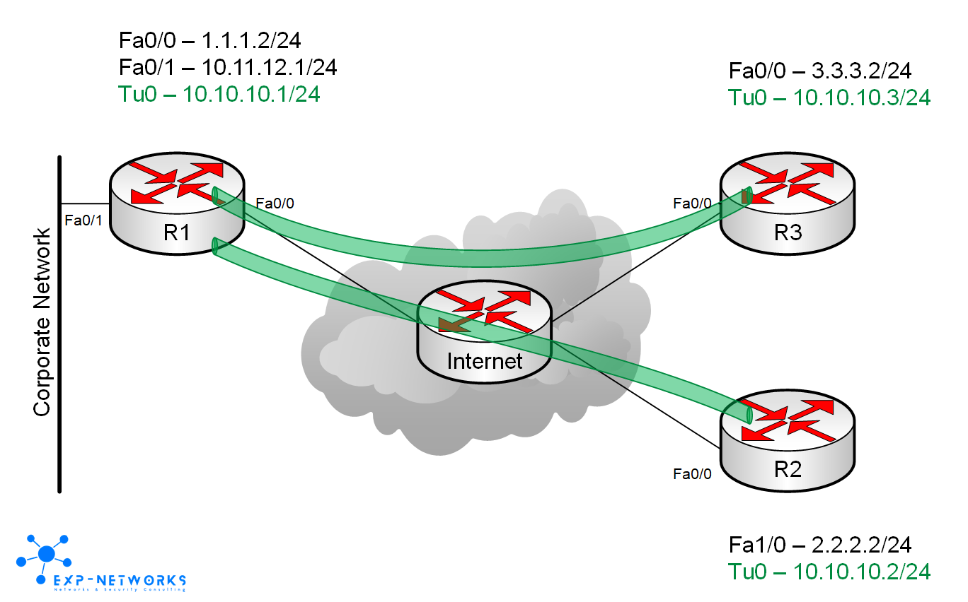
interface Fa0/0ip address 1.1.1.2 255.255.255.0
ip route 0.0.0.0 0.0.0.0 1.1.1.1Spoke routers (R2 and R3 in this example) will use point-to-point GRE tunnel pointing to central site’s hub router R1. NHRP will be configured to use R1 as next-hop server. With this setup, spoke-to-spoke traffic will flow through the hub making the hub a central point where you can enforce security…
Spoke router R2:
interface Tunnel0ip address 10.10.10.2 255.255.255.0ip nhrp map 10.10.10.1 1.1.1.2ip nhrp network-id 1ip nhrp nhs 10.10.10.1tunnel source FastEthernet0/0tunnel destination 1.1.1.2tunnel key 1interface Fa0/0ip address 2.2.2.2 255.255.255.0ip route 0.0.0.0 0.0.0.0 2.2.2.1
Spoke router R3
interface Tunnel0ip address 10.10.10.3 255.255.255.0ip nhrp map 10.10.10.1 1.1.1.2ip nhrp network-id 1ip nhrp nhs 10.10.10.1tunnel source FastEthernet0/0tunnel destination 1.1.1.2tunnel key 1interface Fa0/0ip address 3.3.3.2 255.255.255.0ip route 0.0.0.0 0.0.0.0 3.3.3.1
At this stage, if the router can communicate with each others via their Fa0/0 interface then the GRE tunnels are usable. In this example, “Internet” router is directly connected to all the routers and the routers R1, R2 and R3 simply have a default route pointing to the “Internet” router.
To check the GRE tunnels are operational, we only have to ping the tunnels’ internal IP from one router to the others two.
R2#ping 10.10.10.1Type escape sequence to abort.Sending 5, 100-byte ICMP Echos to 10.10.10.1, timeout is 2 seconds:!!!!!Success rate is 100 percent (5/5), round-trip min/avg/max = 272/313/420 msR2#ping 10.10.10.3
Type escape sequence to abort.Sending 5, 100-byte ICMP Echos to 10.10.10.3, timeout is 2 seconds:!!!!!Success rate is 100 percent (5/5), round-trip min/avg/max = 312/564/876 ms
If we check the NHRP entries on the hub R1, we can see the two entries have been learned dynamically and the public IP used by the remote routers.
R1#sh ip nhrp10.10.10.2/32 via 10.10.10.2, Tunnel0 created 00:11:31, expire 01:48:28Type: dynamic, Flags: authoritative unique registered usedNBMA address: 2.2.2.210.10.10.3/32 via 10.10.10.3, Tunnel0 created 00:08:19, expire 01:51:52Type: dynamic, Flags: authoritative unique registered usedNBMA address: 3.3.3.2
Same info without the timers…
R1#sh ip nhrp briefTarget Via NBMA Mode Intfc Claimed10.10.10.2/32 10.10.10.2 2.2.2.2 dynamic Tu0 < >10.10.10.3/32 10.10.10.3 3.3.3.2 dynamic Tu0 < >
Statistics about the NHRP protocol itself
R1#sh ip nhrp trafficTunnel0Sent: Total 30 Resolution Request 0 Resolution Reply 0 Registration Request3 Registration Reply 0 Purge Request 0 Purge Reply0 Error IndicationRcvd: Total 30 Resolution Request 0 Resolution Reply 3 Registration Request0 Registration Reply 0 Purge Request 0 Purge Reply0 Error IndicationR1#sh ip nhrp summaryIP NHRP cache 2 entries, 496 bytes0 static 2 dynamic 0 incomplete
On the spoke routers we can check the same… Here we can see the NHRP entry is statically defined
R3#sh ip nhrp10.10.10.1/32 via 10.10.10.1, Tunnel0 created 00:13:31, never expireType: static, Flags: authoritativeNBMA address: 1.1.1.2
R3#sh ip nhrp summaryIP NHRP cache 1 entry, 248 bytes1 static 0 dynamic 0 incomplete
And we can check the NHRP’s next-hop server used.
R3#sh ip nhrp nhsLegend:E=Expecting repliesR=RespondingTunnel0:10.10.10.1 RE
Should you want to allow spoke-to-spoke tunnels to be built dynamically, you only need to replace the tunnel destination 1.1.1.2 command on the spokes by tunnel mode gre multipoint making the spokes’ tunnel interface an mGRE interface. For the remaining of this article, we won’t use mGRE interfaces on the spokes.
Now that we have IP connectivity, we still have to secure those dynamically created GRE tunnels with IPSec. Here for simplicity we will use pre-shared key as authentication method which is not recommended for production deployment…
On the hub and spoke routers, just configure ISAKMP/IPSec parameters and enable IPSec on the tunnel insterfaces.
crypto isakmp policy 10authentication pre-sharecrypto isakmp key cisco123 address 0.0.0.0 0.0.0.0!crypto ipsec transform-set mySet esp-aes esp-sha-hmac!crypto ipsec profile myDMVPNset security-association lifetime seconds 120set transform-set mySetset pfs group2
interface Tunnel0tunnel protection ipsec profile myDMVPN
Check IPSec SA are well negotiated
R1#sh crypto ipsec sainterface: Tunnel0Crypto map tag: Tunnel0-head-0, local addr 1.1.1.2protected vrf: (none)local ident (addr/mask/prot/port): (1.1.1.2/255.255.255.255/47/0)remote ident (addr/mask/prot/port): (2.2.2.2/255.255.255.255/47/0)current_peer 2.2.2.2 port 500PERMIT, flags={origin_is_acl,}#pkts encaps: 121, #pkts encrypt: 121, #pkts digest: 121#pkts decaps: 121, #pkts decrypt: 121, #pkts verify: 121#pkts compressed: 0, #pkts decompressed: 0#pkts not compressed: 0, #pkts compr. failed: 0#pkts not decompressed: 0, #pkts decompress failed: 0#send errors 0, #recv errors 0local crypto endpt.: 1.1.1.2, remote crypto endpt.: 2.2.2.2path mtu 1500, ip mtu 1500, ip mtu idb FastEthernet0/0current outbound spi: 0xA2BC2FED(2730242029)inbound esp sas:spi: 0x2884EDEA(679800298)transform: esp-aes esp-sha-hmac ,in use settings ={Tunnel, }conn id: 2005, flow_id: SW:5, crypto map: Tunnel0-head-0sa timing: remaining key lifetime (k/sec): (4463708/83)IV size: 16 bytesreplay detection support: YStatus: ACTIVEinbound ah sas:inbound pcp sas:outbound esp sas:spi: 0xA2BC2FED(2730242029)transform: esp-aes esp-sha-hmac ,in use settings ={Tunnel, }conn id: 2004, flow_id: SW:4, crypto map: Tunnel0-head-0sa timing: remaining key lifetime (k/sec): (4463708/82)IV size: 16 bytesreplay detection support: YStatus: ACTIVEoutbound ah sas:outbound pcp sas:
That’s it! The DMVPN setup is ready for wide deployment… Of course central hub router should be duplicated for redundancy, it will exposed in a future post.
Thanks for leaving a comment if you found this useful